


Use the Newforma Viewer (Markup Editor)
Use the Newforma Viewer to mark up drawings and other files.
Click the following links to go to information on the Newforma Viewer action you want to perform (or scroll down the page):
To navigate a drawing using the Toolbar
1. Use the
five buttons on the right side of the Toolbar to pan and zoom in and out
of the drawing, or click Pan and Zoom
from the Viewer Tasks panel. Click
each icon for more information.

2. Once you have the drawing positioned and sized correctly, you can mark it up and save it as a markup, as explained above in To create markups within a markup session.
To create a new markup session
1. Open the Newforma Viewer using one of the following methods:
● Select a drawing file, then click Open with Newforma Viewer from the File Tasks panel of most Project Center activity centers.
● Double-click a .DWG, .DGN, .DWF, .DXF, or .PDF file from any activity center in Project Center.
● Right-click
on the Newforma
Project Center Tray Tool icon  ,
then select Snapshot to run the
Newforma Snapshot Tool. Capture
the section of the screen you want to mark up. The screen capture opens
in the Newforma Viewer.
,
then select Snapshot to run the
Newforma Snapshot Tool. Capture
the section of the screen you want to mark up. The screen capture opens
in the Newforma Viewer.
● To create a new markup when the Newforma Viewer is already open, click File, Open. Locate and double-click the file you want to open. Navigate through the drawing as explained in To navigate a drawing using the Toolbar.
2. Do one of the following in the Newforma Viewer:
● Click Markup Drawing to open the Markup Tools panel to create a new markup based on the source file you just opened.
● To edit an existing markup, click View > Show the Drawing Explorer to open the Drawing Explorer dialog box, click the Views tab, then select the markup you want to modify from the list.
You can create as many markups as you want for each drawing. Just click Save Current View as Markup from the Markup Tools panel for each new markup you want to save. Each version is added to the Drawing Explorer dialog box.
Click Delete Selected Views in the Drawing Explorer dialog box to delete the selected markups.
3. Continue with the next section.
To create markups within a markup session
Markup sessions are made up of individual markups. You can create a series of markups during a markup session. You can preview and browse them in the Markup View panel, which you can also use to add comments or to quickly view each markup. Markups are also accessible from the Views tab of the Drawing Explorer dialog box.
1. From
the Viewer Tasks panel, click
Markup Drawing to open the Markup Tools panel and choose
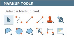
the shape tool you want to use, as shown here:
Remember, you are not editing the actual source file. Project Center uses the file as the background for the markup. No changes are made to the actual drawing.
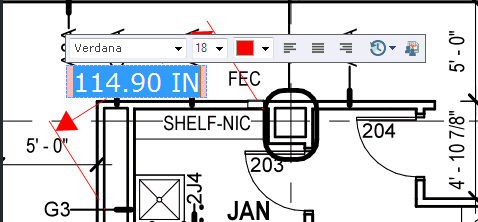
2. When
adding lines, freehand shapes, rectangles, or ovals to the drawing, choose
the pen type to use from the Markup Tools
panel:
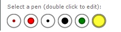
You can choose from six pen styles. To customize the appearance of the
pens, double-click the pen you want to modify to open the Tool
Style dialog box. You can choose from many options to create different
markers (solid lines) or highlighters (transparent lines).
You can also customize all six text styles by double-clicking the pens to access the text tools in the Tool Style dialog box.
3. Place the cursor on the spot where you want to insert the drawing object (or text) and click and drag to draw the object, or type the text.
4. When finished, click Save Current View as Markup to add the markup to the Markup View panel to save it.
Click the  button if you want to remove markups from the from the Markup
View panel.
button if you want to remove markups from the from the Markup
View panel.
5. You can continue creating as many new markups for the currently open drawing file as you require. Click Save Current View as Markup for each markup you create.
To insert a screen image from the clipboard
You can capture an image of the screen and paste it onto a markup session.
1. Right-click
on the Newforma
Project Center Tray Tool icon , then select Snapshot to run the Newforma
Snapshot Tool.
2. Press and hold the Alt key while clicking and dragging to capture the section of the screen you want to insert on the markup. Release the mouse button, then the Alt key. The screen capture is saved to the clipboard.
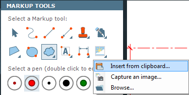
3. From
the Markup Tools panel, click
the image icon and select Insert from
Clipboard, as shown here:
4. From
the Insert Image panel, mark the
Apply Annotation Scale checkbox
if you want the inserted image to have the same scale applied to it that
text created with the text tool  does. This means
that screen shots containing text at specific font sizes will be scaled
to match the same font size of text inserted using the text tool.
does. This means
that screen shots containing text at specific font sizes will be scaled
to match the same font size of text inserted using the text tool.
5. Position the image box in the location you want and click the mouse button to place it.
To save markups
1. You can save the current markup exactly as it appears (including zoom and pan positions and any markups) by doing any of the following:
● Click Save Current View as Markup from the Markup Tools panel.
● Click Save Current View as Markup from the Views tab of the Drawing Explorer dialog box. The name of the saved markup is highlighted in the Drawing Explorer dialog box. You can click markups from the list to display them in the Newforma Viewer.
● Click
the  button in the Edit
Text tool when adding markup text to the drawing to create a markup
after the text is added.
button in the Edit
Text tool when adding markup text to the drawing to create a markup
after the text is added.
2. Whichever method you use saves the markup and adds it to the Markup View panel. If you save it from the Edit Text tool, the name of the markup is the same as the text that was added. If not, the current markup is scanned for any markup text to use as the default name. If none is found, it assigns a default name, such as Markup 1.
● You can rename a markup by clicking on the markup's name in the Markup View panel to edit it.
● You
can delete a markup by clicking the
button to the right of the markup's name.
To save a markup session
After you finish your markup session, you must save it to a project to allow all Project Center users to review and comment on your markups. Perform the following steps to save a markup session:
1. From
the Newforma Viewer Toolbar, click
the  button to open the Save
Markup Session As dialog box.
button to open the Save
Markup Session As dialog box.
2. The name of the file is entered in the Name field. You can edit it.
The session is automatically saved to the current project.
3. Click Members to open the Choose a Project Team Member dialog box to select project team members to include in the markup session.
4. Enter any keywords, if applicable.
5. Enter any comments about the markup session in the Remarks tab.
6. If you are marking up a drawing related to another project item, click the Related Items tab, then click Relate to > Another Project Item to open the Select Project Item dialog box, and then select the Project Center item to relate the source drawing to. This is important if you are using document sets for a red line set review, for example.
7. Click
OK to create and save the markup
session to the project.
After you save the markup session, Project Center users can interact with
each markup in the session without the need to open the markup session
in the Newforma Viewer. Using the Project
Markup Sessions activity center or the Related
Markup Sessions activity center, project team members can browse thumbnails
of each markup, see a list of related items, and add comments to the markups.
To add callouts and leaders
1. Click Markup Drawing from the Viewer Tasks panel.
2. Click
![]() and then select
and then select  to add a callout and leader.
3. Click on the item you want the arrow to point to (the arrow is placed first) and then drag to the location you want to place the callout.
4. Enter the callout text and format it, and then click outside of the callout to insert it on the drawing.
To count objects and measure lengths and areas
1. Click
Count and Measure from the Viewer Tasks panel (or the  button
from the Toolbar).
button
from the Toolbar).
To measure length
Click Measure
Length to measure lengths within the drawing. Next, click  to measure a straight line; press and release Ctrl to measure arcs; click
  to measure a multiple point line; click
  to select and measure existing objects in the drawing. Click and drag
the lengths you want to measure within the drawing. The measurements are
shown in the Results panel. You
can click the items in the Results
panel to highlight them in the drawing.
to select and measure existing objects in the drawing. Click and drag
the lengths you want to measure within the drawing. The measurements are
shown in the Results panel. You
can click the items in the Results
panel to highlight them in the drawing.
● Mark the Subtract Length from Total checkbox if you want to subtract subsequent lengths (to create a negative measurement).
● Click the Unit of Measure drop-down list to select the unit of measurement in which to display the results of a measurement (inches, feet, etc.). Important: For the measurements to be calculated accurately, the drawing unit of the source drawing must be set correctly. The Drawing Unit is located at the bottom left of the Newforma Viewer. The Unit of Measure setting allows you to convert the drawing measurement from a value based on the current drawing unit to a different unit of measurement. For example, if the Drawing Unit is Inches and you measure a length of 30 inches, the result will be calculated based on the selection you make in the Unit of Measure field. If you select a Unit of Measure of Feet, then the result of 30 inches will be converted and displayed as 2.5 feet.
● In the Results panel, mark the Zoom to Selected Item checkbox, then click an item from the list to zoom in on it.
● The results of the addition and subtraction of lengths are calculated in the Total field.
● Click Clear Results to remove all measurements from the Results panel and from the markup.
● Click Remove the Selected Item to remove the item highlighted in the Results panel and from the drawing.
● Click Home when finished.
To measure an area
Click Measure
Area to measure areas within the drawing. Next, click  to measure a rectangular area; click
  to
define the area by clicking points in the drawing; click
to
define the area by clicking points in the drawing; click  to
select and measure existing areas in the drawing. Click and drag over
the areas you want to measure within the drawing. The measurements are
shown in the Results panel. You
can click the items in the Results
panel to highlight them in the drawing.
to
select and measure existing areas in the drawing. Click and drag over
the areas you want to measure within the drawing. The measurements are
shown in the Results panel. You
can click the items in the Results
panel to highlight them in the drawing.
● Mark the Subtract Area from Total checkbox if you want to subtract the subsequent areas (to create a negative measurement).
● Click the Unit of Measure drop-down list to select the unit of measurement in which to display the results of a measurement (feet, meters, etc.). Important: For the measurements to be calculated accurately, the drawing unit of the source drawing must be set correctly. The Drawing Unit is at the bottom left of the Newforma Viewer. The Unit of Measure setting allows you to convert the drawing measurement from a value based on the current drawing unit to a different unit of measurement. For example, if you measure an area of the drawing, the result will be calculated based on the selection you make in the Drawing Unit field. If you select a Unit of Measure of Square Feet, the result of the selected area will be converted based on the drawing unit.
● In the Results panel, mark the Zoom to Selected Item checkbox, then click an item from the list to zoom in on it.
● The results of the additions and subtractions are calculated in the Total field.
● Click Clear Results to remove all measurements from the Results panel and from the markup.
● Click Remove Selected Area to remove the highlighted item from the Results panel and from the markup.
● Click Home when finished.
Click the  button (located in
the Toolbar) to snap to drawing objects when measuring. (PDF files must
be vector based for snap to work.)
button (located in
the Toolbar) to snap to drawing objects when measuring. (PDF files must
be vector based for snap to work.)
Linear and area measurements are inaccurate when measuring 3-D views of drawings.
To count objects
Click Count
to count objects in the drawing. Next, click  to count
objects manually (one at a time), or click
to count
objects manually (one at a time), or click  to count
multiple objects of a similar type automatically.
to count
multiple objects of a similar type automatically.
Automatic counting only works with DWG files.
● To count items manually, click on items in the drawing. A checkmark is added to the item. The items are numbered and shown in the Results panel.
● To count items automatically, place the cursor over the type of item you want to count. All matching items in the drawing are highlighted. Click to count all of the highlighted items. A checkmark is added to each of the items. The items are numbered and shown in the Results panel. You can click the items in the Results panel to highlight them in the drawing.
● In the Results panel, mark the Zoom to Selected Item checkbox, then click an item in the panel to zoom in on it.
● The total number of items appears in the Total field.
● Click Clear Results to remove all items from the Results panel and check marks from the markup.
● Click Remove Selected Item to remove the highlighted item from the Results panel and from the markup.
● Click Home when finished.
The Newforma Viewer does not save counts. They are cleared when you click Back.
To calculate and overlay dimensions
You must set the drawing scale on image and PDF files before using the dimension tools; refer to To measure length in the To count objects and measure lengths and areas section above. You do not need to specify the scale for CAD drawing files (DWG/DGN/DWF/PLT) as the scale is read from the drawing file.
1. Click
Markup Drawing from the Viewer Tasks panel (or the ![]() button from the Toolbar).
button from the Toolbar).
2. Click
 to access the following tools to calculate and add dimensions to the drawing.
Click the button (located in
the Toolbar) to snap to drawing objects when measuring. (PDF files must
be vector-based for snap to work)
To calculate and overlay linear dimensions
● Select
 to calculate and add linear (horizontal and vertical) dimensions to the
drawing.
to calculate and add linear (horizontal and vertical) dimensions to the
drawing.
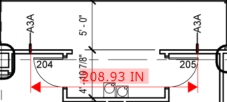
● Click the first point you want to measure from.
● Click the second point you want to measure to.
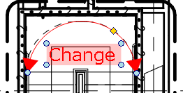
● Drag
the cursor up, down, or side to side to the location where you want to
insert the dimension and the callout and click. The Newforma Viewer calculates
the dimension and automatically inserts it. You can erase the dimension
value simply by typing, or you can add more text to it by clicking next
to the dimension value and typing. You can also use the  tool to move just the dimension
text, or to adjust the placement of the dimension. An example with the
dimension text moved is shown here:
tool to move just the dimension
text, or to adjust the placement of the dimension. An example with the
dimension text moved is shown here:
● Click Home when finished.
To calculate and overlay aligned dimensions between any two points
● Select
 to calculate and add aligned dimensions between any two points on the
drawing, no matter the angle.
to calculate and add aligned dimensions between any two points on the
drawing, no matter the angle.
● Click the first point you want to measure from.
● Click the second point you want to measure to.
● Drag
the cursor to extend the dimension out to the desired distance and click.
The Newforma Viewer calculates the dimension value and automatically inserts
it. You can erase the dimension value simply by typing, or you can add
more text to it by clicking next to the dimension value and typing. You
can also use the tool to move just the dimension
text, or to adjust the placement of the dimension. An example with the
dimension and the text tool with the callout is shown here:
● Click Home when finished.
To add angular dimensions
● Select
 to add angular dimensions to the drawing.
● Click the first point you want to measure from.
● Click the second point you want to measure to.
● Drag
the cursor to create the desired radius and click. You can add text to
it by typing. You can also use the tool to move just
the dimension text, or to adjust the placement of the dimension end points.
An example with the dimension text moved is shown here:
● Click Home when finished.
To find text in the markup drawing
1. Enter
text you want to search for in the Find
field (located in the Toolbar at the top of the Newforma Viewer),
then click Find. The results appear
in the Drawing
Explorer dialog box. Click an item in the Text
column to zoom in on it. Click the ![]() button
to zoom back out.
button
to zoom back out.
The Find feature finds text created in the actual drawing, as well as any text added using the Markup Tools panel.
Find applies only to the current drawing. Use Project Center's Search feature if you want to search for text across an entire project or multiple projects.
The Find feature does partial string matching on each
individual term in the Find string, not whole word matching like the Search feature.
If you type in Africa hall concrete,
Find will return any text that contains any of those words, such as "ABC
Africa 123" or "marshall."
If you type in "Africa hall concrete"
(in quotes), Find will return any term containing that compound phrase,
including "ABC Africa hall concrete
123."
The Viewer Find feature does not find text, such as phrases, discovered via the OCR scanning process.
2. Close the Drawing Explorer dialog box when finished.
To compare two drawing revisions and add a legend
This feature enables you to compare the baseline source drawing to a drawing revision. The current drawing is used as the baseline. You can also add a color legend using this feature.
When you compare drawings, any markups that were added are included with the source file in the comparison.
1. From the Viewer Tasks panel, click Compare to open the Select Revised Drawing dialog box.
2. Locate and select the drawing you want to compare to the baseline (currently open) drawing, then click Open.
3. The drawings
are shown overlaid on each other. Use the following tools to compare the
drawings.

The Compare Tasks panel contains
the following comparison tools you can use:
Change Tolerance
Optional: To ignore changes below a certain value, enter the value in the Change Tolerance field. Changes smaller than the tolerance value will be ignored.
Animate Differences Between Baseline and Revised Drawing
Use the Baseline-Revised slider to show the change between the baseline and revised files graphically. When the slider is in the middle, the drawings are overlaid on each other. Move the slider to the left to show the baseline drawing. Move the slider to the right to show the revised drawing.
Digital Light Table
Click to compare the drawings using the Digital Light Table. The Digital Light Table opens with the two drawings overlaid on each other. It provides a pixel-level comparison where:
● Pixels that exist in both drawings are dimmed and represented as gray;
● Pixels that exist in the baseline drawing but were removed from the revised drawing are colored red;
● Pixels that were added to the revised drawing but do not exist in the baseline drawing are colored blue.
Modify Comparison
Click to open the Modify Comparison panel to access the following tasks:
● Align Drawings (and scale them)
● Fit Revised to Baseline
● Original Drawing Alignment
● Compare Model Space Only
● Accept Revised Drawing
● Revert to Previous Drawing
● Swap Baseline and Revised Selections
● Back to Compare Tasks
Home
Click when finished comparing to return to the Viewer Tasks panel.
On rare occasions, two .DWG files may not automatically align correctly. This could happen if an AutoCAD DVIEW or TWIST command was applied to a drawing. If this happens, use the Align Drawings task to align them.

The Compare Legend panel displays the color code representing what objects were changed, not changed, added, and removed, as well as original and revised object locations.
The Compare Legend panel appears only when comparing .DWG and .DXF files.
Added
Blue objects in the revised file are objects that were added to the revision since the baseline.
Removed
Red objects in the baseline file are objects that were removed in the revised version.
Not Changed
Gray objects were not changed in the revised file from the baseline.
Original Location
Magenta indicates the original location of objects in the baseline file that were moved in the revised file.
Revised Location
Green indicates the new location of objects in the revised file that were moved since the baseline.
Insert a Color Legend
Click to open the Insert Legend panel to select a location in the drawing to add the color legend described above. Adding a legend can make it easier for other users to understand what each color represents.
Change Legend Text
Click to open the Properties dialog box to add a title and set the font for the legend.
To compare three or more drawings at the same time
This feature enables you to compare three or more drawings to each other. You can also add a color legend using this feature.
1. In Project Center, locate the drawings you want to compare and select them using the Shift or Ctrl keys.
2. Click Compare with Newforma Viewer from the Tasks panel to open them in the Newforma Viewer.
3. The baseline
drawing is shown. Use the following tools to compare the drawings.

The Compare Revision History panel
displays the comparison tools you can use.
Use Slider to Animate Between Adjacent Versions of Files
Use the slider to show the change between the baseline and revised files graphically. When the slider is directly over a drawing icon, only that drawing is shown, and it becomes the baseline. The drawing to the right becomes the revision. When the slider is between two drawing icons, the drawings are overlaid on each other. Move the slider to the left to show the baseline drawing. Move the slider to the right to show the revised drawing.
Digital Light Table
Click to compare the drawing using the Digital Light Table. The Digital Light Table opens with the drawings overlaid on each other. It provides a pixel-level comparison where:
● Pixels that exist in both drawings are dimmed and represented as gray;
● Pixels that exist in the baseline drawing but were removed from the revised drawing are colored red;
● Pixels that were added to the revised drawing but do not exist in the baseline drawing are colored blue.
Home
Click when finished comparing to return to the Viewer Tasks panel.

The Color Legend panel displays the color code representing what objects were changed, not changed, added, and removed, as well as original and revised object locations.
Added in Revision
Blue objects in the revised file are objects that were added since the baseline.
Removed in Revision
Red objects in the baseline file are objects that were removed in the revised version.
Not Changed
Gray objects were not changed in the revised file from the baseline.
Original Location
Magenta indicates the original location of objects in the baseline file that were moved in the revised file.
Revised Location
Green indicates the new location of objects in the revised file that were moved since the baseline.
Insert a Color Legend
Click to open the Insert Legend panel to select a location in the drawing to add the color legend described above. Adding a legend can make it easier for other users to understand what each color represents.
Change Legend Text
Click to open the Properties dialog box to add a title and set the font for the legend.
To align and scale two source drawings to compare them
This feature enables you to align two source drawings to compare them to each other more easily, and to scale two drawings to the same scale.
1. From the Viewer Tasks panel, click Compare to open the Select Revised Drawing dialog box.
2. Locate and select the revised drawing you want to compare to the baseline (currently open) drawing. Click Open.
3. The drawings are shown overlaid on each other. Click Modify Comparison from the Compare Tasks panel to open the Modify Comparison panel.
4. Click Align Drawings to access the Align Drawings panel.
5. To align the drawings, pan and zoom the drawings as desired, then click Move Drawing.
6. Click and drag from a point on the revised drawing (darkened) to the point on the baseline drawing (dimmed) that you want to align to. The revised drawing will align to the selected point on the baseline drawing.
7. To scale the drawings to each other, pan and zoom the drawings as desired, then click Scale Drawing from the Align Drawings panel.
8. Click and drag to specify a known distance on the revised drawing.
9. Click and drag to specify the same distance on the baseline drawing. You will be prompted to align the two drawings to the ends point of the scale. Click Yes if you want to automatically align the drawings. The revised drawing will resize to fit the scale selected for the baseline drawing. If you chose to align the drawings, they will align to the scale endpoints.
To print the drawing and set the printing scale
1. From
the Newforma Viewer Toolbar, click the  button.
2. Configure the Print Options panel, including the page range, orientation, and which printer to use.
3. Do one of the following:
● Choose Current Page to print the current page as is.
● Choose Custom View, then use the mouse to resize and position the printing box over the area of the drawing you want to print. If you choose this option, the Select Region or Scale panel appears, from which you can select a value from the Scale drop-down list.
The Scale drop-down list provides a number of common drawing scales in architectural or decimal units. Choosing a standard scale from the panel resizes the printing box to reflect the selected scale. You can then select the center grip to move the printing box over the exact region you want to print. You can also select and stretch one of the corner grips to resize the printing box. The Scale value in the Select Region or Scale panel updates accordingly.
If the drawing has multiple viewports of differing scales, then the printing scale will be disabled. Also, if the drawing unit of the drawing is not inches (as set in the Source File Settings panel), the Architectural Units checkbox will be disabled.
● Click Save Current View if you want to save the current markup and the selected print area.
● Click Restore View to return to the previously saved markup and print area.
4. Click Print to print the page. Click Home when done.
To email the current markup
1. You can email the current markup exactly as it appears (including zoom and pan positions) by clicking Email Current View from the Viewer Tasks panel or from the Markup Tools panel.
2. A new Microsoft Outlook email message opens containing the markup, which is saved in a .PNG file attachment. The email message also contains a link to the original drawing. Edit the email and click Send.
For better quality when emailing a drawing containing markup text, create and send it as a PDF.
To save or send the drawing as a .PDF file
Sending your markup session as a .PDF files is useful when you know the recipient does not have Project Center. After marking up a drawing, you can quickly create and send a .PDF of the markup session to another external user as follows:
1. From
the Viewer Tasks panel, click
Create or Send PDF or click the
 button.
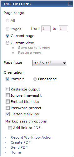
2. Configure
the PDF Options panel, shown here,
as necessary, including the page range, paper size, and the page orientation.
You can also send a mark up of the whole sheet or page or configure a
smaller, custom markup.
3. Do one of the following:
● Choose All to save all pages to a .PDF file.
● Choose Pages to save a page range to a .PDF file.
● Choose Current Page to save only the current page to a .PDF file.
● Choose Custom View, then use the mouse to resize and position the printing box over the area of the drawing you want to save or send. If you choose this option, the Set Region or Scale panel appears, from which you can select a value from the Scale drop-down list.
The Scale drop-down list provides a number of common drawing scales in architectural or decimal units. Choosing a standard scale from the panel resizes the printing box to reflect the selected scale. You can then select the center grip to move the printing box over the exact region you want to print. You can also select and stretch one of the corner grips to resize the printing box. The Scale value in the Select Region or Scale panel updates accordingly.
If the drawing has multiple viewports of differing scales, the printing scale will be disabled. Also, if the drawing unit of the drawing is not inches (as set in the Source File Settings panel), the Architectural Units checkbox will be disabled.
● Click Save Current View if you want to save the current markup.
● Click Restore View to return to the previous markup.
To save an AutoCAD drawing with multiple tabs to a PDF file, choose the page range you want to publish. Each tab becomes a page in the PDF.
4. Mark the Rasterize Output checkbox to create a raster-based .PDF file instead of a vector-based .PDF file. It's similar to taking a screen capture and saving it as a .PDF. This option is available for printers that don’t support transparency.
If the Rasterize Output option is checked when publishing to a .PDF file, a raster-based .PDF will be created where the DPI will be set to the value set in the registry. To prevent excessively large raster images from being created (when a large paper size, such as 36” x 48” is selected), the size of the raster image is limited to 4 million pixels (2000 x 2000). This maximum value is set in the registry.
5. Mark
the Ignore Lineweight checkbox
to ignore the drawing line weights and render them the smallest size possible
to prevent overlapping in .PDFs. This is the recommended method.
For example, in the Newforma Viewer,
a line weight of two pixels appears as two pixels on the screen for AutoCAD
and Microstation files, no matter how much you zoom in or out. As you
zoom in or out, the line appears the same width. PDFs don’t follow that
rule. As you zoom into a .PDF, the line becomes thicker. This becomes
a problem when you try to publish a large, detailed AutoCAD drawing to
a .PDF. In a .PDF, the lines become thicker and overlap each other as
you zoom in. For example, if you have a line weight of 10, and two vertical
lines at x = 0 and x = 5, the lines will overlap in a .PDF. Use this feature
to prevent that from happening.
6. If the
markup session contains hyperlinks, mark the Embed
File Links checkbox to embed the actual file into the .PDF file.
Marking this checkbox takes any hyperlinks to Project Center items (such
as submittals) and embeds the items in the .PDF as HTML files. Other files
that are linked to are also embedded into the .PDF file. Recipients can
then click on the links in the .PDF to open a copy of the linked file
embedded inside the .PDF. Note that embedding files can potentially make
the .PDF file much larger, depending on the sizes of the files embedded.
If this checkbox is not marked, standard hyperlinks to files are inserted
in the .PDF file. Hyperlinks to Project Center items open the item in
Project Center when users double-click the links.
7. Mark the Password Protect checkbox to open the Set PDF Password dialog box to protect the .PDF file from unauthorized access. (The dialog box opens when you click Create PDF).
8. Mark the Flatten Markups checkbox to" flatten" the markups, which means they are not placed on a separate annotation layer in the resulting .PDF. If the checkbox is cleared, the markups are written to a separate annotation layer, which enables Project Center to add some data to the markup, including who created it and when.
9. Mark the Add Link to PDF checkbox to place a link in the markup session that will directly open the new .PDF file when users double-click the link. The link will be labeled Link to File: filename.pdf.
The link will not appear in the .PDF file.
10. Do one of the following:
● Click Record Workflow Action to open the Save PDF as Workflow Action dialog box to save the .PDF file to contract management item. The .PDF file will be added to the item as an action.
● Click Create PDF to open the Save dialog box to save the selected pages as a .PDF file.
● Click Send PDF to open the Send PDF dialog box to choose whether to send the .PDF file via Info Exchange (from which you can optionally log the transfer as a transmittal), as an attachment in a Microsoft Outlook email message, or via a drag and drop method (if available).
Click Home when finished.
If the markup session contains any saved markups, the markups associated with each markup session are created in the .PDF as bookmarks. If you send a .PDF of a markup session containing many individual markups, the recipients can easily navigate to the each markup using the bookmarks. You might want to alert recipients to use the bookmarks to access all of your markups.
When creating a .PDF file, markups are saved to the annotation layer of the .PDF file. This enables users to select them to track who created them and when.
To manage drawing visibility (hide items)
This feature enables you to select objects individually, by layer, or by type, and make them invisible.
1. From the Viewer Tasks panel, click Manage Drawing Visibility.
2. From the Drawing Visibility panel, choose whether you want to select objects By Layer, By Object Type, or Individually.
3. Move the cursor over an object that you want to make invisible.
If you are selecting objects By Layer or By Object Type, all objects that match the chosen object are highlighted and selected automatically.
4. Click an object to make it invisible. All highlighted matching objects also become invisible. Invisible objects turn gray while you are using the Drawing Visibility panel. Click any gray objects again to return them to normal visibility.
5. Optional: Under To Aid in Selection, Hidden Objects Are, choose Not Displayed if you want to make the selected objects completely invisible instead of gray.
6. Click Accept Changes to apply the visibility settings and return to the Viewer Tasks panel. All gray objects will be made invisible and will remain that way until you click Reset Drawing Visibility, which resets the drawing to its original state.
To customize colors and other viewer settings
This feature enables you to set the background color, object colors, animation speed, pattern fill transparency, snap, and pattern placement of the markup.
1. From the Viewer Tasks panel, click Options to open the Options dialog box.
2. To change the background color of the drawing, click the Viewer Background Color box and choose a new color.
3. To change the color of all objects in the drawing to the same color, mark the Monochrome Background Geometry checkbox, then click the color box and choose a color from the palette.
This feature does not change the color of the markups added to the drawing.
This option may not have an effect if the background drawing is already drawn with a black and white plot style.
4. To set the Background Lineweight Scale, move the slider to the left to make drawing lines thinner, or to the right to make them thicker.
5. Mark the Enable Warning Message Window to allow warning messages to appear when a problem occurs.
6. Use the
Snapshot Format field to select
the file format in which to save and send screen captures when you click
the  button from the Toolbar.
7. Mark the Consistent Markup Text and Line Weight checkbox to scale the text and line weight for markups. See To scale markup line weight below.
8. Mark the Display Open Markup Sessions checkbox to open the Drawing Explorer dialog box to the Markup Sessions tab when a new file is opened in the Viewer. The Markups tab shows all markups that have been created for the file.
9. Clear
the Use Ctrl or Shift to Add to
Selection checkbox to add subsequently
selected markup objects to the selection set when you use the
tool from the Markup Tools panel.
As you click on markup objects, the previously selected objects will remain
selected, which is the same as using the Shift
key while selecting multiple objects.
● If you select object A, then select object B, object A remains selected.
● If you select objects A and B and want to remove object B from the selection set, hold down the Shift key and pick object B to remove it and keep A selected.
● You can de-select objects by pressing the Esc key or right clicking the mouse.
Conversely, if you mark this checkbox, only one object will remain selected at a time. If you select object A, then select object B, object A will be de-selected. To select multiple objects in this case, press the Shift key while selecting objects.
10. Mark the Snap to Background Geometry checkbox to snap to objects in the drawing when adding markups and using the measurement tools.
PDFs must be vector-based for snap to work.
11. To change the Zoom Speed, move the slider to the left to slow it down, or to the right to speed it up. This affects features such as the zoom speed.
12. Click OK when finished to apply the changes.
To manage the source drawing
This feature enables you to select a different source drawing, set the drawing unit, choose an AutoCAD layout, or set the drawing scale.
1. From the File menu, click Source File Settings to open the Source File Settings dialog box.
2. The current
source drawing is listed in the Current
Source File field. Click the  icon to open the Change
Source File dialog box to select a different source drawing.
icon to open the Change
Source File dialog box to select a different source drawing.
3. Choose the drawing unit to use with the drawing from the Drawing Unit drop-down list.
4. Optional:
For .DWG and .DXF drawings, click the 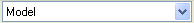 drop-down list at the bottom of the Newforma Viewer to select a different
AutoCAD layout tab.
drop-down list at the bottom of the Newforma Viewer to select a different
AutoCAD layout tab.
For raster images, .PDF files, and .DWF files, use the Set Drawing Scale dialog box to set the scale for the image to generate accurate linear and area measurements. Refer to the next section.
5. Click OK when finished.
To set the drawing scale
Use this feature to set the scale for raster files, .PDF files, and .DWF files.
1. From the Viewer Tasks panel, click Count and Measure, then click Measure Length or Measure Area.
2. Click Yes when the message appears to specify the scale.
3. Pick two points on the drawing for which you know the actual distance and click and drag a line between them. The Set Drawing Scale dialog box opens.
4. Enter the distance in the Actual Distance field, then click OK. Lengths for this drawing are now based on the value you entered here.
To insert a color legend and set the visibility of drawing changes
This feature enables you to insert a legend in the drawing.
1. From the Viewer Tasks panel, click Compare.
2. Locate and select the revised drawing you want to compare to the baseline (currently open) drawing. Click Open.
3. From the Compare Legend panel, click Insert a Color Legend to add a legend and set the legend properties.
4. Click at the position you want to insert the legend. After the legend is inserted, you can click on it to resize it.
5. Optional: click Change Legend Text to open the Properties dialog box to add a title and set the font for the legend.
To view markup sessions for a drawing
This feature enables you to locate and view all saved markup sessions for the current drawing.
1. From the Viewer Tasks panel, click Show Drawing Explorer to open the Drawing Explorer dialog box.
2. Click the Markup Sessions tab, which lists all markup sessions that have been created for this drawing.
3. Mark the checkboxes of the markups you want to view. They will be inserted on the drawing.
To scale markup text and line weight consistently
This feature enables you to scale markup text and line weights either consistently for all markups of a drawing, or differently for each markup of the drawing.
1. From the Viewer Tasks panel, click Options, to open the Options dialog box.
2. In the Markup section, mark the Consistent Markup Text and Line Weight checkbox to draw the next markup object that you add to the drawing to the scale of the current markup. All subsequent markup objects are then drawn to the scale of that first object added after this checkbox is marked, regardless of the zoom factor of the current markup.
Marking this checkbox does not affect any previous markup objects.
● When you mark the Consistent Markup Text and Line Weight checkbox, the first markup object added to the markup session is drawn to the scale of the current markup, and the scale of all subsequent markup objects in the drawing will be consistent to that scale. This is beneficial when printing a marked up drawing and you want a consistent text and line weight applied to all markups.
● When you clear the Consistent Markup Text and Line Weight checkbox, each new markup object is scaled based on the current markup. As you zoom in and out to create different markups of the drawing, the text and line weights are scaled relative to each markup. This is useful when creating markups at different zoom or scale factors and saving markups for each markup. If you send the markups as bookmarks in a .PDF or as individual images, the text and line weight scaling will be consistent for each markup. However, if you print the whole marked up drawing, the markup text and line weights will not be consistently scaled. Their scales will differ in appearance based on the zoom level in which they were added.
3. Click OK when finished.
To set the annotation scale for markups
This feature enables you to re-scale existing markups and set the scale for all subsequent markups. This is useful if existing markups that you want to either send, publish to a PDF file, or print are too big or too small. It is also useful if you have created inconsistently scaled markups and want to reset them all in the same scale, or if you use a 120 DPI monitor.
1. From the Viewer Tasks panel, click Markup Drawing.
2. In the Markup Tools panel, click Set Annotation Scale to access the Set Annotation Scale panel.
3. There are four ways to reset the annotation scale: click and drag; select an existing markup object; scale to current view; or scale objects individually. Each option is explained below. The first three are accessed from the Set Annotation Scale panel.
Click and drag (as explained in the instructional text)
The first way is to click and drag anywhere in the drawing. Clicking and dragging dynamically previews the text font and height. As you drag the cursor, the text height changes. After selecting the second point, you are asked if you want to update all markup objects.
● If you answer Yes, all existing markup objects are re-scaled to the new scale.
● If you answer No, none of the existing markup objects are re-scaled. However, if the Consistent Markup Text and Line Weight checkbox (as explained in the To scale markup text and line weight consistently section above) is marked, the scale factor of all subsequent markups will be changed to the new scale.
● If consistent scaling is off (the Consistent Markup Text and Line Weight checkbox is cleared), you are asked if you want to activate consistent scaling so that all subsequent markups in the drawing are consistent. If you answer Yes, consistent scaling is activated, and the Consistent Markup Text and Line Weight checkbox is automatically marked.
Select an Existing Markup Object
Click this task to re-scale all markup objects in the drawing to a markup object you select. When you select the object, you are prompted update all markup objects.
● If you answer Yes, all existing markup objects are re-scaled to the scale of the selected object.
● If you answer No, none of the existing markup objects are re-scaled. However, if the Consistent Markup Text and Line Weight checkbox (as explained in the To scale markup text and line weight consistently section above) is marked, the scale factor of all subsequent markups will be changed to the new scale.
● If consistent scaling is off (the Consistent Markup Text and Line Weight checkbox is cleared), you are asked if you want to activate consistent scaling so that all subsequent markups in the drawing are consistent. If you answer Yes, consistent scaling is activated, and the Consistent Markup Text and Line Weight checkbox is automatically marked.
Scale to Current View
Click this task to re-scale all markup objects to the current markup. If the objects were created in different markups, use this option to scale them all to a specific markup before publishing or sending the markup. When you select this option, you are prompted to update all markup objects.
● If you answer Yes, all existing markup objects are re-scaled to the scale of the current markup.
● If you answer No, none of the existing markup objects are re-scaled. However, if the Consistent Markup Text and Line Weight checkbox (as explained in the To scale markup text and line weight consistently section above) is marked, the scale factor of all subsequent markups will be changed to the new scale.
● If consistent scaling is off (the Consistent Markup Text and Line Weight checkbox is cleared), you are asked if you want to activate consistent scaling so that all subsequent markups in the drawing are consistent. If you answer Yes, consistent scaling is activated, and the Consistent Markup Text and Line Weight checkbox is automatically marked.
Scale individual markup objects
The fourth way to set the annotation scale is
to set it for individual markup objects. From the Markup
Tools panel, click the
tool, select the markup objects that you want to re-scale, then click
the Set Annotation Scale task.
Click and drag anywhere in the drawing, or use one of the two tasks above
to set the annotation scale for the selected markup objects.
To rotate raster images
You can rotate raster image files (.BMP, .JPEG, .GIF, .TIFF, .PNG, and .PDF files) in 90 degree increments. Click View, Rotate Current Background Page or View, Rotate All Background Pages, then select the increment. Any markups that have already been added are not rotated.
To remove a stamp from the stamp drop-down list
To remove a stamp from the list, click the  button
in the Markup Tools panel,
place the cursor over the name of the stamp, then press Delete,
as shown here:
button
in the Markup Tools panel,
place the cursor over the name of the stamp, then press Delete,
as shown here:
To copy and paste text from PDF files
When a PDF file is open, click Edit
> Select PDF Text (or click the  button),
select the text, and then click Copy
Text to Clipboard. You can then paste the text wherever it needs
to go.
button),
select the text, and then click Copy
Text to Clipboard. You can then paste the text wherever it needs
to go.
To use keyboard shortcuts
Keyboard shortcuts are available for some functions. Simply click the menu items at the top of the window. If a keyboard shortcut is available, it is listed next to the command. For example, you can click Edit, Undo, or use the keyboard shortcut Ctrl-Z.
Table of Contents
Index
Search (English only)
Back